
#125🚀 DC/DC Push-Pull Converter
Deep dive in Power Electronics from Silicon Valley

👋 Hello Amigos! Dr. Molina here 👨🔧
Happy New year!! I hope you have had time to enjoy the time with your family and friends and you haven´t enter in arguments with your father in law about politics, it’s once per year… don´t talk about politics during Christmast!
This year I would love to be more consistent on delivering newsletters and probably, more focus on Power Electronics, I’ll try it!
During this first edition I’ll bring you what I learnt due to a customer meeting where he was using Push-Pull.
During this edition I’ll share my learnings about this converter and I’ll use another topology I know better as a reference, the Phase Shift Full Bidge.
Push-Pull vs Phase-Shifted Full Bridge
I have choosen six aspects to analyze the Push-Pull and compare it with the PSFB
Operation
Transformer design
ZVS
IC for analog control
EMI
Cost
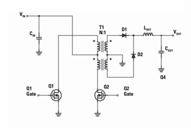
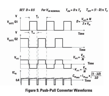
1. Push-Pull Operation
The Push-Pull converter has two switches and two primary windings in the transformer that connects Vin to each winding alternatively, generating a square +Vin and -Vin, with a zero interval waveform in the transformer.
Due to the configuration, voltage across switches is 2 x Vin.
The seconday is a center tap rectifier configuration that transform the negative pulses in positives (doubling the frequency) before the L-C filter.
This pulsating signal is filtered by a L-C filter generating the constant DC voltage in the output.
2. Transformer
The transformer of the push-pull is as well used as the transformer of the PSFB, the only difference is the center tap in the primary, which could add some complexity in the production respect to a unique primary.
What differs between both is how robust the volts x second balance is in practice. Let me go a little bit further here, to have avoid saturate the transformer, you have to ensure applying the same time and volts in the positive cycle than in the negative, so, you get zero DC flux, which will cause saturation.
In Push-Pull, volt-second balance relies on two separate switch intervals matching precisely. Real-world mismatches (driver delay, MOSFET differences, dead-time asymmetry) cause DC flux offset unless compensated.
In PSFB, the phase shift modulation makes much easier avoiding the saturation, because the positive and the negative cycles are generated by the same phase shift and most of the problems could come from layout and discrete components problems.
This means that the risk of saturating the transformer in the Push-Pull is not zero and the hardware implementation will have an impact. In small designs, I saw designers taking enough margin to avoid that problem.
3. Zero-Voltage Switching (ZVS)
ZVS is one of the most important traits for high-efficiency converters. It reduces switching losses by ensuring that MOSFETs turn on when their drain-to-source voltage is near zero, lowering stress and heating.
To achieve ZVS, you need:
Enough inductive current at the end of a switching interval
A current path during dead time that forces the switching node to swing and discharge capacitances (such as MOSFET Coss)
Push-Pull has inductance (magnetizing + leakage), but the current is not forced into the commutation path during dead time. That means ZVS is not natural; ZVS in Push-Pull is coincidential or accidental, it’s not a charateristic of the topology.
PSFB, by contrast, has the natural connections that force current through the nodes where the parasitic capacitances are charged. That structural property makes ZVS achievable across a wider load range.
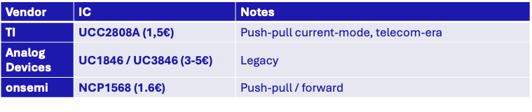
4. IC selection
These are the ICs in the market for Push-Pull and the prices, as you can see, there are very affordable options.
Push-Pull Options
Phas Shift Full Bridge Options

5. EMI
The EMI has been one of the most repeated questions from the audience for this article-
Push-Pull tends to generate smoother common-mode noise at moderate power because it has fewer floating high-dv/dt nodes. This will reduce CM noise. Nevertheless, not having ZVS increase the DM noise.
PSFB, with floating bridge midpoints and multiple switching nodes, complicates CM EMI. However, you have ZVS, what reduce DM
6. Cost
On cost, Push-Pull has fewer switches and simpler drivers, while PSFB incurs more parts but often compensates with better efficiency and thermal performance at higher power.
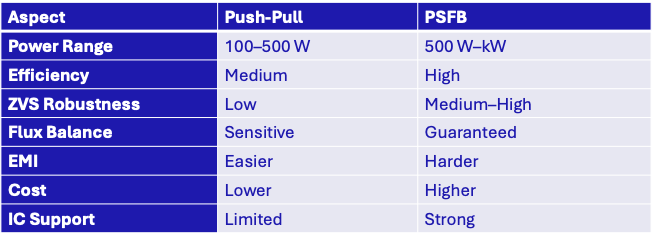
7. Conclusions and Summary
The Push-Pull range of use is narrowing with the years, but still there are some applications where it could be the best option. In the following table, I try to compare it with the PSFB and assuming Flyback and Forward will be the options for lower power ratios.
My only concern is the IC technical support, I would speak with a supplier to verify which tech support I can get from them.
Thank you, Jonny, for your help editing this article.
Thanks for reading! I would love to listening your feedback about this edition and what topics about converters and magnetics you are more interested in.
These are some of the most read editions of the newsletter:


Excellent breakdown of the Push-Pull vs PSFB comparison. The commutation path analysis for ZVS is spot-on - that forced current circulation during dead time in PSFB is what makes it predictable across load ranges. I designed a 2kW telecom supply a few years back where we initialy chose Push-Pull for cost reasons, but the unpredictable ZVS behavior at light loads killed our efficiency targets. The volt-second imbalance issue you mentioned was also a constant headach during prototyping tho.