#94🚀 Understanding Proximity losses with Ampere's Law
SuperPowers for Electrical Engineers 🦸🏻♂️🦸🏼♀️
👋 Hello, friends! Dr. Molina here 👨🔧
Having scientists like Jonas around helps me better understand the physics behind each model we use to design magnets.
A few days ago, I asked him to explain to me again how to construct the loss model in the 2D winding, and before we started, he said:
"Chema, the most important thing before we begin is to understand this equation, Ampere's Law."- Jonas Mühlethaler
∮H dl=∬J dA
This equation tells you that if you draw any closed-loop path in any space, the sum of all H components along this line is equal to the sum of the electric currents that are passing through this loop.
Understanding Ampere’s law is fundamental for understanding the skin and proximity effects to calculate winding losses in high-frequency magnetics and model them.
If we try to analyze the losses in an ungapped transformer with two windings based on several layers of foil wires, as in the picture, there are two basic types of losses on the windings.
DC losses due to the resistivity of the cooper (We continue dreaming with superconductors…remember this post? This is easy: take the current, the area, and the length of a wire, and you can use the analytical equation:
Pcu= Rdc x I^2
Losses due to High Frequency or Eddy Currents losses (in the end, everything is about Eddy Currents). We typically divide the losses into two effects, calculated separately: skin effect and proximity.
Let’s talk about proximity.
Understanding Proximity Losses with Ampere’s Law
To calculate the Proximity losses in a transformer of two windings, we can´t isolate the layers or the windings and then sum up all of them. We need to calculate the resultant magnetic field due to the currents flowing through the conductors and their position.
And here is where we use Ampere´s law. With Ampere´s law, you can analyze the intensity of the magnetic field in the window of your transformer, as you can see in the drawings of my CTO, Jonas Mühlethaler.
Here, we are considering that the core has an infinite permeability; therefore, the intensity of the field there will be H=0.
The evolution of the H field in the window grows due to the current of Winding 1 (blue) and starts decreasing when we arrive at Winding 2, whose current direction is opposite Winding 1. We can see here how the current through a conductor generates a magnetic field, which produces so-called eddy currents in the other conductors. This leads to additional losses.
The H field increases once we cross the conductor; however, we use the average value to simplify the loss calculation.
With this field representation, The losses now can be calculated with the following equation:
P= Gf(f) Rdc Havg^2
Gf(f)→ It’s a factor that depends on the conductor's geometry and frequency.
Rdc→It’s the DC resistance of the conductor.
Havg→It’s the average value of the magnetic field intensity in each conductor.
Until here, you can say, well, so what! That’s all? It’s easy to calculate the proximity losses! Sorry, my friend, this is for ungapped magnetics.
Proximity effect with Gap
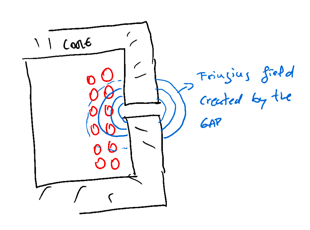
Once you have a gap in the core, everything gets crazy. Including a Gap leads to a change in the magnetic field in the core window, which impacts the conductors, increasing the losses.
I’m about to explain the modeling strategy Jonas used in his thesis to calculate the proximity losses with round or litz wires where there is a Gap.
This technique is called Mirroring
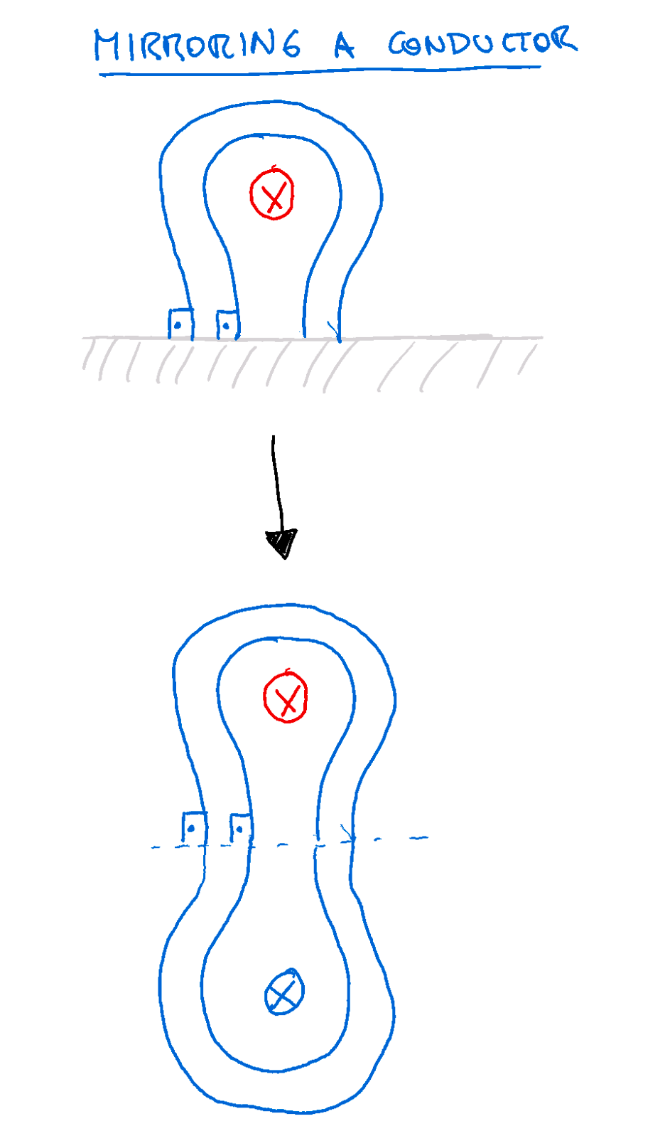
Before continuing, let me explain the mirror technique.
When you have a conductor close to a surface (a core) with infinite permeability, the magnetic field lines have a 90º angle with the surface. So, suppose we remove that surface and place another conductor at a symmetric distance concerning the initial surface. In that case, we have the same magnetic field lines and effect, but we don´t need to consider the effects of the core in the Ampere’s law analysis.
Are we ok until here? Let’s continue.
When you have a Gap, an additional magnetic field impacts your conductors.
As a solution to consider the gap, we can substitute that gap with an equivalent conductor, and use the mirror technique to simplify the calculations of the H fields.
This is what Jonas proposed in his thesis. Place conductors instead of gaps and remove the core (the surface), placing equivalent conductors in a symmetric structure. You can mirror as many times as you want. The main goal is to isolate the area you want to study from the effects of a surface with infinite permeability, creating more complexity during the analysis. Once you are far away from the core, you can calculate the proximity effect considering the gaps.
I know this is not easy to understand.
However, the implementation at Frenetic Online was even harder. Having Jonas and the best software talent took us several months, plus one month of testing.
That’s all for today; I expect you have enjoyed this edition as much as I have.
Special thanks to Jonas for his lessons 🤗.
Previous Posts about this topic:
#1 🚀 USA trip and Rac resistance- Part I 🧵
#2 🚀 California, Magnetic Designer, Rac resistance Part II 🧵 and Beta Version
If you missed….some of the most widely read articles in the Dr.Molina Magnetics Newsletter:


