#8 🚀 How to design a 600W Power Supply Full Bridge Transformer, Product Design and Community
The Newsletter of High Frequency folks
👋 Hello! Dr. Molina here! 👨🔧
Thank you for reading and welcome to the show my Newsletter. Today I will focus on the design of a Transformer for a reference design from Texas Instrument.
First I will talk a little bit about Product and community 🚀.
Product Design in Power Electronics
I discovered the beauty of the “Design” discipline 3 years ago. Design is everywhere. The chair you are sitting on right now, has been designed by someone, the mouse, the glass (the wine inside too), lamps (there is a very famous spanish designer, Miguel Milá).
Actually, as engineers, we spend half of our professional lives designing things but we are not aware of that. I look back and I realize how many things I have designed and I didn´t think:
-Ey, they [PCB, Power Supply, Mathcad file…] will be used by someone else, let’s think about his experience!
Usually, the thoughts were more like this:
-Is this [whatever] working? Ok, let’s move on.
After being aware of the beauty of a good design, I’m obsessed with the design of everything at Frenetic and we still have a long 2022 to really help engineers to do the work of one month in a day.
We take care of the visual design of the Simulator, the design experience, the Onboarding process, the Onboarding material, the Samples, the box where we put the samples…
Right now, we`re working on the Industrialization support. After a design is created by an engineer, we will help him to translate the digital component into an industrial component. Any volunteer to test our Beta?
I’ll continue posting about Product Design. Last comment: my favorite designer is Jonathan Ive (Apple)
Community
I did a survey on Linkedin about creepage and clearance and here are the results. So, I will talk about this topic in this Newsletter.
Additionally, the famous Bryce Hesterman has published in our community!! Here is the link.
How to design a 600W Power Supply Full Bridge Transformer
I love Power Electronics and I will dedicate my whole professional life to building projects that accelerate the progress and the implantation of new technologies. Remove barriers between engineers’ ideas and their prototypes.
One of my worst nightmares, when I was doing the Ph.D., was to find all the components of a Bill of Materials (BOM) of a reference design. Especially, the most difficult components to find were usually the magnetic components.
So, 10 years later, working on a project with a friend (and customer) I found a reference design that could be used as a template for the power supply. We found this reference design from TI of a 600W Full Bridge Phase Shift and after a general review, I ended looking for the transformer(s) in the BOM and this is what I find:
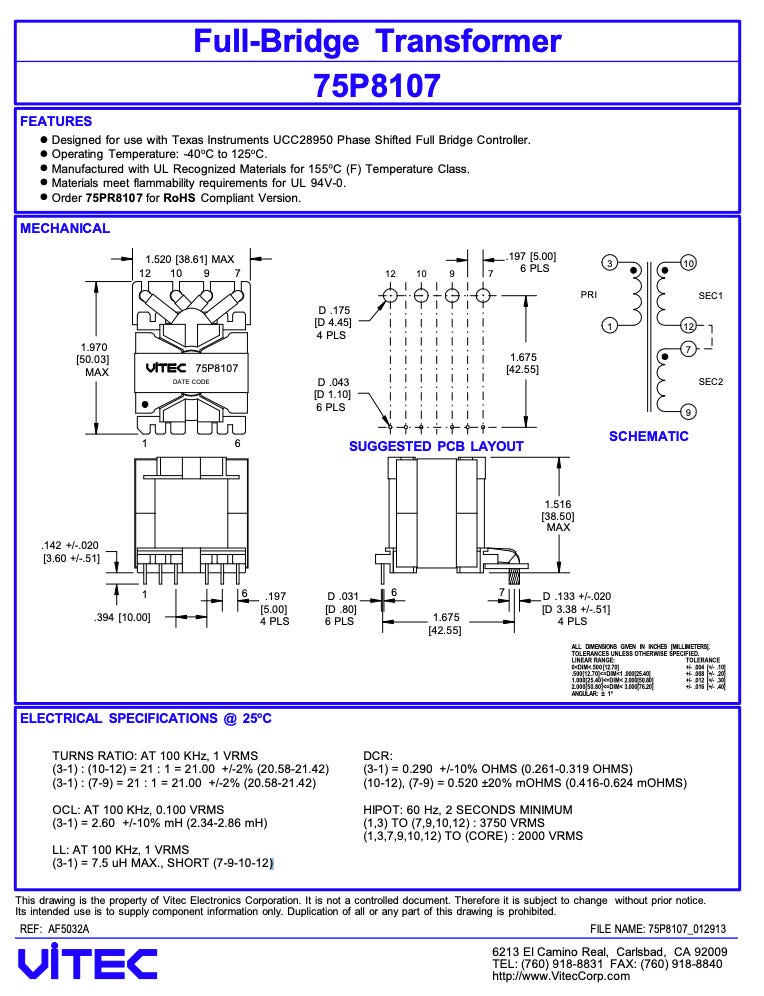
T2; part number 75PR8107; from Vitec Electronics.
If you take the part number and visit the Vitec Electronics website, you won´t be able to download anything, but….if you search deeper in the datasheets pages, you will find the datasheet below. If you try to purchase one, it’s not possible.
Then, I’m going to build my equivalent component, same size and similar footprint (without customization of the coil former) and I will share it with all of you 🤓 (your welcome 😊)
First Step: Specifications
First of all, I’m going to review the power supply specifications. I could just try to replicate the component reading the inductances, turn ratios and isolation test, but, since I’m not like the classic consultants, with an incredible gut feeling and intuition about what works and what doesn´t, I prefer to have some simulation results.
Therefore, the Power Supply basic specifications (this is a reference design, not a commercial power supply, which will need a lot of more electrical, safety, reliability, mechanical and functional requirements):
Reference Design Features
• 400V DC input (370Vdc to 410Vdc operation), 12V DC output
• Peak efficiency greater than 95%. Above 90% efficiency down to 10% load
• 50 Amp (600 Watt) rated output • Phase Shifted Full-Bridge Circuit topology
• 100 kHz switching frequency
• Peak Current Mode Control (PCMC) with no external support circuitry for PCMC function
• Multiple Synchronous Rectification (SR) switching schemes
• Adaptive ZVS/LVS across the complete load range
• Efficient GUI Interface that allows fast & easy system tuning for optimal performance
• Fault protection: Input UV and OV, Over-current, Output UV (CC/CP mode)
• Constant current (CC) and constant power (CP) functions
• Optional Voltage Mode Control (VMC)
The features in bold have a direct impact on the transformer design but still, we need to define isolation and mechanical requirements. Other requirements I have found in the transformer datasheet are:
Second Step: Isolation
My customer requirements are:
Reinforced isolation
Industrial application
Working at a lower altitude of 2000 m
Pollution degree II
I will follow standard 60664-I for calculating creepage and clearances.
Not idea about what creepage and clearances are? Here some links of great material:
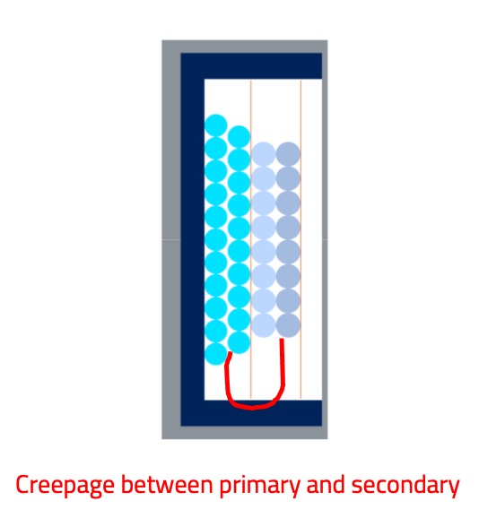
Creepage is the shortest distance between windings or between windings and the core (can be different values) along of a solid isolation material. The next pictures ilustrate the creepage (red line) between primary and secondary. This is the reason, why using the whole window area is a problem when you have some isolation constrains. As we will see, this space will be ocupied by “Margin tape”.
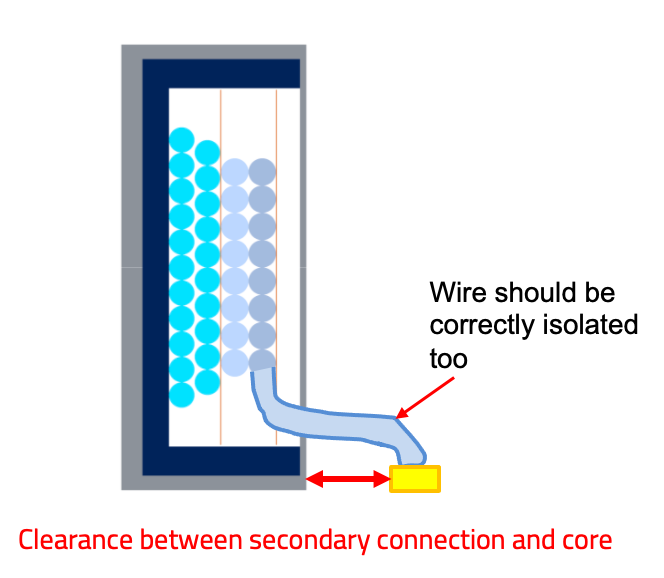
Clearance is the distance between two windings through the air, when there are two windings in the same layer or between the core and the final conections of the winding. When there is a isolation tape between windings, there is no clearance value between windings. In the picture below, you can see the typical case in a Flyback, where you need to isolate the final connection and the core.
TIP1: Creepage value should be always equal or higher than Clearance.
TIP2: The reinforce isolation move you to the next restricted level inmediatly in the clearance and double the value for the creepage.
I know this is can be complex and I’m just a user, not an expert. You can ask some of Frenetic experts or watch this video of Wurth
In order to provide a similar design in terms of isolation of the TI reference design, I will check the transformer document. Here you can see their electrical specs:
What we can take here is:
Turns ratio 21:1
Magnetizing inductance Lm=2,6mH (+/-10%)
Leakage Inductance, Llk=7,5uH (This value is used for ZVS in the Full-Bridge Phase Shift, in this link you can learn more about it)
Series resistance W1=0,261-0,319 Ohms; W2=0,416-0.624 Ohms)
Vac Isolation test is done at 60Hz, 2 seconds at 3750 Vrms between primary and secondary, and 2000 Vrms between windings and core (In this case, the core won´t be connected to any ground, something very common in Flyback converters)
Now, we find to calculate the creepage and clearance values from the tables of 60664-I. There are some flux diagrams to follow, like this one.
However, I’m going to show you directly the tables where I’m selecting the values.
Rated Impulse Voltage
For selecting the clearance and creepage, we need to find the Rated impulse voltage. According to this table, where we can´t extrapolate, our input DC voltage is 400 V, we have to select the 600V value. According to the customer overvoltage category, II, this value is 4 kV.
Clearance
Now I will select the Clearance value, for 4 kV. It will be 3 mm, but since it’s reinforced, we need to move to the next level, then, it will be 4 mm.
Creepage
Now, I will find the creepage value. The Material group will be I and the RMS voltage 400 V (It’s 375V but I will assume 400V), the creepage value is 2 mm, but for reinforced isolation, we have to double this number, therefore it will be 4 mm.
Summary
Since clearance is higher than creepage, the final values are:
Rated Impulse Voltage = 4 kV
Creepage = 4 mm
Clearance = 4 mm
Build the design
With all this information I go to Frenetic.ai (You can create an account for free and use the 1-week free trial to follow my steps or load my project) and I create a New Project. Then, I select Transformer and Full-Bridge, and Center Tap.
Then, I introduce all the values found before, for building the waveforms and the platform will create the waveforms automatically. I won´t include noise, because the PCB will be great 😜.
In the advance inputs, I include some data of the isolation (it’s just information to be recorded in my design) and the cooling conditions, natural convection.
Disclaimer -This information is not used by the design generator, it will be used in the industrialization process.
Core Selection
In the datasheet, you can find see the core size and looks similar to a PQ40/40, therefore, I chose: Ferrite technology, PQ40/40 and 3C95 as material. Since the turn ratio is 21, I will try 21 turns in primary, to have just 1 turn in secondaries. The Lm resultant is within the tolerances (2,42 mH).
IMPORTANT!!
“If you are not an expert, in the next steps I recommend you to verify the result with an expert. The industrialization of a component is a complex task” Myself.
Frenetic suscription includes the industrialization of the pieces. We translate your ideas into industrial products.
Winding selection
For the windings, I have fixed the turns per winding to 21 for primary and 1 turn for each secondary. I ask for a winding suggestion and here is the result.
As you can see, there is no Margin Tape suggestion (It’s in our roadmap 🚀) and here you need to industrialize the piece. Therefore, the Margin Tape will be mandatory.
In my first review, I see, the primary is ok, however, the secondary’s suggestion is not acceptable for mass production. It could work for a laboratory sample, but not for mass production. Why? Due to the number of parallels, the final diameter of the wire will be even bigger than the core itself….like a monster…here you can see an example of BAD MAGNETIC.
We want to avoid a monster, therefore, I’m going to use foil instead of Litz wire in the secondary. Typical foil width will be 0,3 mm and the heigh for this coil former and considering the margin tape will be 20 mm. You can put all the parallels you want but the cost will increase. I add 2 parallels in total (remember to add layers for each parallel).
IMPORTANT! I will add the Margin Tape (in Yellow), 2 mm in primary and 4 mm in secondary. To comply with the standards.
In principle, this design looks good. Buuuut!! There is some industrialization potential problem…
The primary winding is divided into two layers; therefore, we need to connect somewhere between both layers. Connect both in a pin, is the best option, but it’s including more manual complexity.
Therefore, I’m going to put the two primary layers in parallel, instead of the series. For doing that, I need to change the primary wire to keep an acceptable current density. Rac losses will increase by 0,2W but the cost of manufacturing decrease.
Connecting two layers in parallel is much easier for the production, avoiding flying connections or additional pin connections.
I think this design will work perfectly in the reference design of TI or other Full Bridge Center Tap, in any case, you can simulate the losses to your specific waveforms.
Would you be interested in this design?
Create an account of Frenetic
Write me an email to chema@frenetic.ai from the same account you registered at Frenetic.ai
I will share the design with you
Would you like to order a sample? (59€/unit) There are limited units.
Write me an email to chema@frenetic.ai with the number of samples you need (max. 2 samples per order) and the address to calculate shipping cost.
I will send you a payment link.
I will confirm the order and ship you the components
Also, you can follow this link and book a call with me for a particular case!
Now is your turn! How do you rate this Newsletter?
If you liked it, don´t keep it for yourself and share it with your friends and social network 😍
Do you have any questions or comments? I would be glad of listening to your feedback. Haters first, please 😜.
Top finds🧑🏽🌾
Series: For all Mankind
Book: The Cold Start Problem
Thank you again for reading and don´t forget to subscribe.
Sincerely,
Chema 👋


Thanks for sharing this nice post to understand all those common issues that designers of P.E systems may overcome in their daily lifes, and how the use of Frenetic Online tool can minimize such troubles, simplifying and reducing the process to a great extend!