
#127🚀 Power Electronics tools Part II

👋 Hello Amigos! Dr. Molina here from San Francisco🇺🇸
This is the second part of #126🚀 Power Electronics tools review
I want to start this edition saying thank you for all your comments, sharing and readings from last edition, it really made my day and motivated me to keep learning and sharing with you.
Today we bring the second part of the article, bringing tools to choose components or design custom components. Most of these tools are used in real industrial environments, I would love to learn which other tools you use in your company and why they are good!
After this article, the series will continue with AI tools and complete workflows.
If you want to join interesting discussions about tools and power electronics, I recommend you to join our community at discord, here.
I’m writing this series of articles with my partner in crime, Jonny Church (Thanks buddy).
Workflow for SMPS
In Part I, we presented a generic workflow that engineers use to create power electronics converters. We then discussed some of the tools that are commonly used by engineers in stages 3, 4, and 6. Whilst not comprehensive the purpose is to get a glimpse of the way things are done currently, and as we go through this series we will begin to discuss which of these areas currently use AI, and which have gaps that expose opportunities to improve the process.
As mentioned previously, the design stage could warrant an article itself, so here it is. But first, let’s remind ourselves of the workflow that was presented in the previous article.
Gather requirements/map constraints.
Generate specification.
Deciding the Topology.
Circuit Simulation.
Component design/selection/BOM creation.
Schematic capture & PCB Layout
Let’s start by presenting those tools and approaches that are used currently by many engineers, but that don’t use AI, yet. And more importantly let’s confirm what we mean by the word ‘design’ in this context.
You have chosen your topology, calculated, and simulated values for your critical components. You now have to generate the right (and real) components for your converter. This may include choosing off-the-shelf products, or as is more increasingly common, you may have to produce a custom component that suits your needs and constraints. This is the design stage.
1 Manufacturer Parametric Tools
Using manufacturers’ online parametric tools is a common way to start the design process. Most device manufacturers provide web-based selectors that allow you to filter components, such as power MOSFETs, diodes, inductors, or transformers, based on key electrical and packaging parameters.
Here are some common ones for MOSFETs as an example (beyond Digikey and RS et al):
Whilst these tools are useful, they share a common limitation: they are fundamentally parametric searches. This means you still need to know exactly what you are looking for. What you really want is not just a list of viable options, but an understanding of which option is best for your design. That ultimately comes down to estimating device losses under your specific operating conditions, and judging whether those losses are acceptable.
Whilst over recent years, we haven’t seen much improvement on the way manufacturers help you to decide MOSFET technology, it is quite the opposite with magnetics. Most likely because magnetics are more complex to design.
Some manufacturers have taken their parametric search tools for magnetics and converters and upgraded them to allow you to compare for different topologies and waveforms, and they even give loss estimates. Here are a few examples:
These have improved the process somewhat over the last decade, however there are two main issues. Firstly, you can only view and compare components from the same manufacturer, and secondly they are off-the-shelf parts, which is fine in a good number of scenarios, but often not the most optimal solution for your design. You are generally making a compromise on cost and/or time.
2 Online Calculators
There are a host of online calculators to be used for aiding in the design process, here’s an example of a couple:
I have used things like these in the past, especially in the early stages of my career as a power electronics design engineer. They’re useful when you don’t know the answers and you want to validate what you already know (or think you do). But they will only take you so far, often they are isolated from the rest of your design process and this will not help you in the long run.
3 Integrated Design Environments
Integrated design environments are more specialised tools that support the design of multiple components within a single workflow. Rather than simple parametric filtering, they allow engineers to actively shape the design and explore optimal solutions across a defined design space. A few examples are outlined below.
Summary table at the end.
RidleyWorks
RidleyWorks® is a long-standing and broad power supply design and analysis software package, with a great following. It spans from topology selection/design and simulation, through to control loop and magnetics design support.
Whilst it is not AI (and I’m sure Dr. Ridley would be the first to assure you that it is not), it has helped many engineers to speed up their design iteration processes, whilst encapsulating decades of practical experience.
I have tested this and I see it as one of the best options in the market, because of the depth of the solution. The tool itself has more than 30 years, this has advantages and disadvantages.
The main advantage is the quality of some of the models included, they are mature and stable.
The problem is that most models are coming from the own work of Dr. Ridley and in the last 20 years, there has been a huge improvement on modelling magnetics, as well as materials and shapes. The tool is based on an excel file with macros, so, you don´t have a project storage system, I guess you can do screenshots for each project.
However, I think it’s a very solid tool for engineers.
You can visit the Ridley Engineering website for interesting articles and design advice, and also glean information from Dr. Ridley’s online community on facebook: Power Supply Design Centre.
Accuracy: There isn´t any accuracy article for the magnetics, but the information shared from other users shows high accuracy for control loop estimations.

Comsol
At the other end of the spectrum, COMSOL is a general-purpose multiphysics simulation environment used to design and validate power-electronics systems. Unlike the tools discussed above, it requires the engineer to explicitly define geometry, materials, and boundary conditions, but in return provides highly accurate finite-element analysis across the design space.
COMSOL is not a schematic-level simulator. Instead, it is the tool you reach for when you want to understand where losses are physically generated within a high-frequency transformer, or to quantify parasitics and field distributions in busbars and interconnects. It does not provide fast, high-level answers, but it does provide accurate ones, and is therefore best suited to the later stages of the design process.
Main disadvantage is the complexity and the core losses.
Accuracy: It’s a FEMM tool, high accuracy in winding losses if you use configure the simulations correctly. Medium-Low in core losses.

ANSYS Maxwell
ANSYS Maxwell sits at a similar point on the spectrum to COMSOL. It is a finite-element analysis tool purpose-built for electromagnetic field problems, particularly in magnetics and current-distribution analysis. As with COMSOL, the engineer must explicitly define the geometry, materials, and excitations, and in return receives high-fidelity, physics-based results.
In power-electronics design, Maxwell is commonly used for magnetics validation, AC copper loss and parasitic analysis, and detailed loss mapping to identify hotspots. It is not a schematic-level simulator or a rapid design tool, but a late-stage validation and optimisation tool used when electromagnetic behaviour is critical to performance.
Main disadvantage is the complexity and the core losses.
Accuracy: It’s a FEMM tool, high accuracy in winding losses if you use configure the simulations correctly. Medium-Low in core losses.
")
PExprt
PExprt was part of the Ansys package and it was created and maintained where I did my Ph.D. in CEI-UPM (Madrid, Spain) but in the last update of the electronic package, they have removed the software. I used this software during my Ph.D times and it was great. A lot of options and a direct connection to Maxwell to get accurate losses.
Accuracy: Not updated results. I can´t tell.
 Overview - Jan 29 2023")
SIMPLIS Technologies
SIMPLIS is often described as a simulator, but in practice it functions as a design-oriented environment for switching power supplies, closer in spirit to tools like RidleyWorks than to generic circuit simulators. Beyond analysing behaviour, SIMPLIS actively supports the design of converters by embedding power-electronics knowledge into its workflow, helping engineers move from specifications to a verified implementation.
A key part of this is its MDM (Magnetics Design Module) and Design Verification Module (DVM). These allow engineers to design and size magnetics, such as inductors and transformers, within the context of the converter itself, rather than as an isolated calculation.
The tool checks operating points, stresses, waveforms, and margins against design rules, effectively answering “does this design work?” rather than just “what happens if I simulate it?”. In this way, SIMPLIS is best viewed as a converter design and verification platform, used once a topology has been selected and the engineer wants confidence that component choices, magnetics, and control all function correctly before moving on to hardware or late-stage physics validation.
Accuracy: No public articles about accuracy

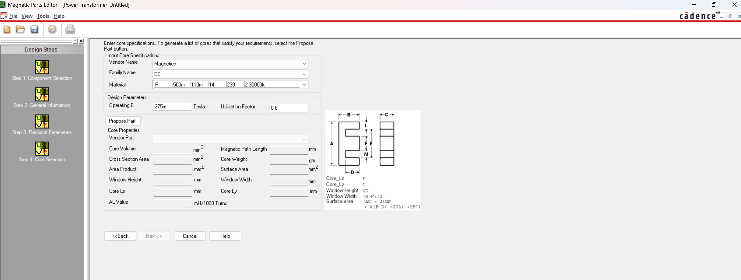
Capture Magnetic Parts Editor
I was surprised when I randomly found this tool from Orcad. My first impression was: This reminds me of PExprt. I started testing it a bit and I saw the tool was a good intent from Cadence to have their own custom magnetics design tool.
The tool can suggest materials but they are not up to date and the topology template list is limited and not very user friendly.
The price probably is zero, because it will be included in the Simulator package (search on your laptop if you have Orcad Capture!)
Accuracy: No public articles about accuracy
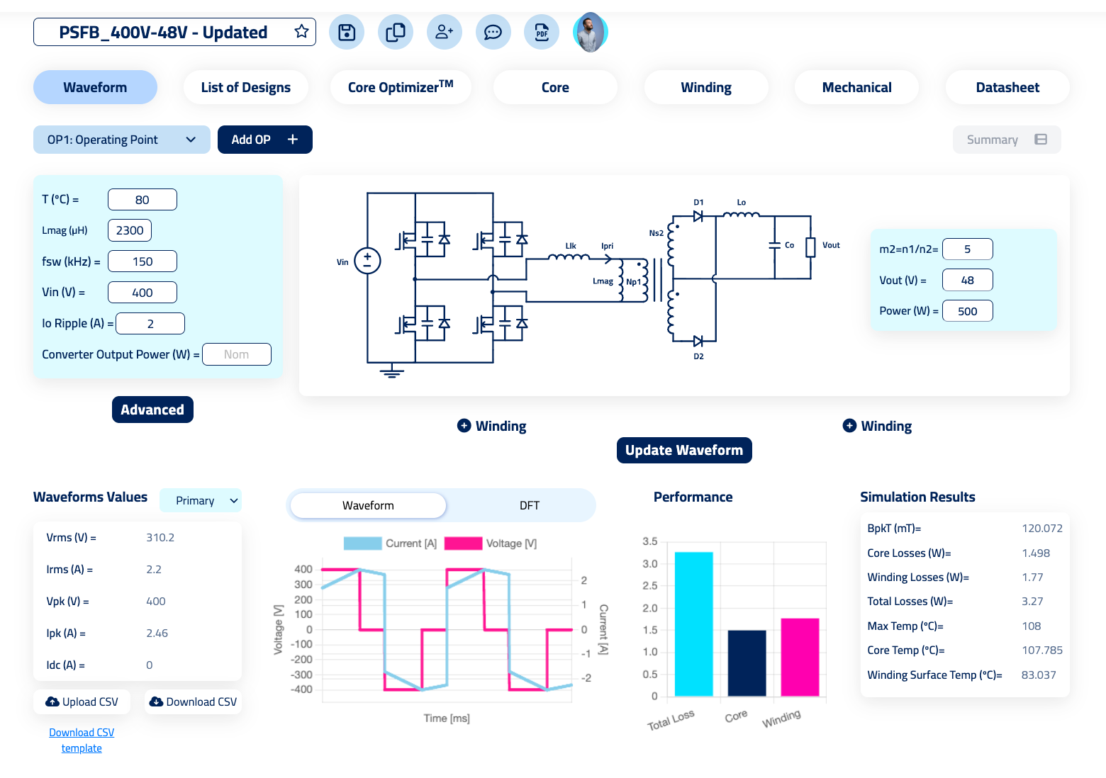
Frenetic Simulator
I could say, this is the best tool in the world! It’s better than all the others! But that’s not true, so I won´t say that.
Frenetic is an online tool for designing and simulating transformers and inductors. Since it’s an online tool, your designs will be on the cloud, (under Cyberessentials security level). Being online allows you to work in collaborative mode.
The tool includes templates based on topologies, having the custom options.
It has limitations in terms of customization of cores and combinations of different types of windings (for example, planar and litz). It only includes two types of cooling (we are working on Liquid cooling, but it takes time). So, when doing an equivalent simulation for something not included, the accuracy in those cases will be lower.
Frenetic published papers about the models implemented (By their scientist Jonas Muhlethaler) as well as datasheets of the models, reporting as low accuracy as 85% in the temperature model.
Accuracy: High accuracy in the range from 100 W to 20 kW and frequencies above 1 MHz. Accuracy articles here.
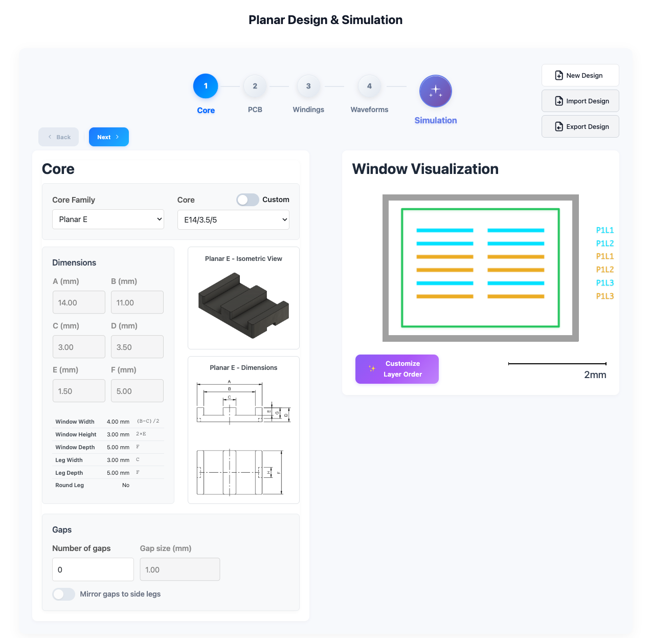
Frenetic Planar
This is a specific software just for simulating planar magnetics. The software requires you to already have a design and it’s very intuitive.
For me, the most interesting part of the software is the system for calculating losses. It uses Comsol online, so it’s running FEM simulations for you online without the need of having any software installed in your laptop.
Accuracy: Professor Ouyang from DTU reported getting the same results with the tool as he did with the designs he created and tested. Lab report in process.
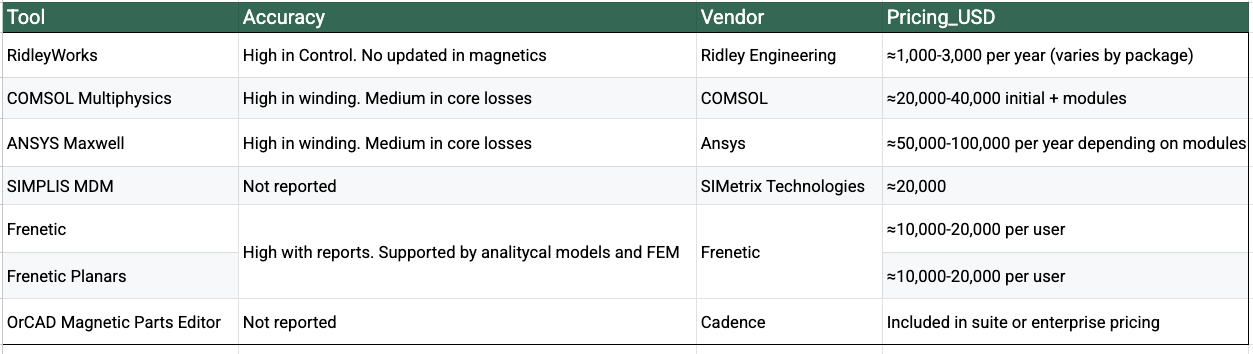
Summary Table
Advising which tool to use in Magnetic design
After a lot of years fighting with the magnetic models, I feel I know very well the options of the industry, I have played with all of them and I’m ready to advise you which option is better for each case.
If you share your use case, I’d be happy to walk you through the likely trade-offs in accuracy, complexity, and overall cost.
Do you have any other ideas? I would love to hear your thoughts in the community chat here!
See you in the community!