👋 Hello, friends! Dr. Molina here 👨🔧
The frequency of this newsletter is not fixed; we are following a variable frequency control like the LLC converters (Monday’s jokes).
The number of customers in the Bay area is so huge that I really don´t have time to sit at my desk.
This week is San Valentine's Day, so I hope you are ready for a lot of love and magnetics ❤️.
Jonas Masterclass in Modeling Magnetics
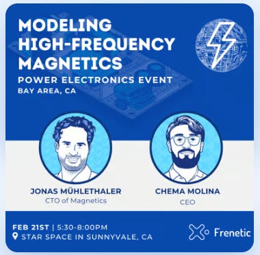
The 3rd Meetup of Power Electronics Community will be our Major event! We will enjoy a Masterclass in magnetics modeling from one of the best scientists in Power Electronics in the world. There is no online broadcasting, no recording, just in-person with Tacos 🥙 in Sunnyvale.
Registrations are open here.
Pentacentra Transformer
The data centers consume more than 1,5% of the electric energy in the US, and researchers have been creating innovative solutions to improve efficiency.
The topology most commonly used during the 2010s has been the LLC.
The Matrix Transformer has nothing to do with the famous movie, but there is some magic there 😉.
More than ten years ago, CPES published some articles and videos about this type of solution for LLC converters, where the idea was to integrate the transformer in the PCB, being very close to the switching devices, allowing very high switching frequencies up to 1MHz.
A new article by Chang Wang from the Technical University of Denmark and from the department led by Professor Andersen was published in TPEL about a new transformer configuration, the Pentacentra Transformer.
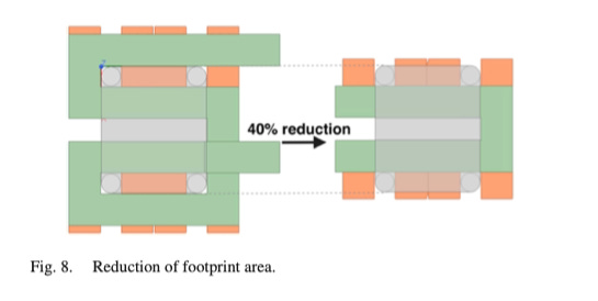
The main difference between the matrix and the Pentacentra is a central bar serving as the fifth leg of the core. The goal of adding this additional leg is to reduce by 40% the layout of the windings in the PCB. From my perspective, I would say it increases the complexity of the core, decreases the complexity of the PCB layout, and improves the overall efficiency.
The article explains with all detail the position of the rectifiers in the secondary, the current flowing paths.
They use the material ML91s from Hitachi. Very popular material in high-frequency publications.
GaN vs Si-FET
Another exciting thing that came out with the experimental results of the article is the comparison between the two prototypes. One uses GaN devices, and the second one uses Si. It's the same board size.
The author explains that he needed to stop the test at 450 W in the GaN case because the device’s heat dissipation was worse than the Si-FET.
GaN devices are smaller than Si-FET, so, the heat dissipation capacity is smaller. Finally, he finished the tests with the Si-FET devices reaching 98% efficiency and 96% at full power. I would love to see if there was a way of improving the GaN heat dissipation without increasing the cost.
Reference
[1] “Pentacentra Transformer for Multiphase LLC Converter in High-Current Data Center Application” Chang Wang , Student Member, IEEE, Mingxiao Li , Member, IEEE, Ziwei Ouyang , Senior Member, IEEE, Tiberiu-Gabriel Zsurzsan , Member, IEEE, and Michael A.E. Andersen , Member, IEEE


