👋 Hello! Dr. Molina here! 👨🔧
Thank you for reading and welcome to the jungle my Newsletter about my journey at Frenetic and my favorite topic, High-Frequency Magnetics 🚀.
This is the First edition of my Newsletter, which means, that I’m looking for your comments, suggestions of topics, and feedback to provide more interesting comments to you (High-level audience 😎). This first one is delivered on Sunday by exception.
🌵 Disclaimer! Before hurting anyone, I write ✍️ with humor, and I can make mistakes, don’t take me too seriously 😉.
Can I ask for french fries? 🍟
I’m writing these words in an aircraft road to San Francisco 🇺🇸. It’s a very special trip. After almost 2 years of the COVID, I didn’t see the moment to finally take this flight.
I have been dreaming of building my company in Silicon Valley so many times. There is a kind of attraction, that every Electrical Engineer or Startup feels to come here.
And yes, I’m nervous, because I know how difficult and competitive this land is. I had my first trip here 5 years ago. I was young carrying a Mac 💻 , my iPhone 📲 and 3 contacts. After some coffees, I don’t know how, but I was invited to present my project at that time (SpCard, a universal PWM generator) in front of a few investors. I was invited to be in the port at 12:30. I arrive on time, dressed in my white shirt and my contact appears with his 14 years old son. Before entering the restaurant, my contact, who had already sold a semiconductor company, says:
-Chema, you are lucky! I have invited 2 facebook investors to meet you, just explain to them your project.
What!!! 🤯!! OMG. I remember the moment, I felt excited, confident.
We arrived at the table, after some introductions and I started doing a presentation about my project. Probably, the worst presentation they had ever seen. I talked about some technical details, no context, no market…and one of the guys, asked me:
-If I understood correctly, you are an expert on Power Supplies and you have something to help some engineers to accelerate their designs. But, honestly, I don´t think apple, building millions of electronics, will really feel this product as a x100 improvement. Why don’t you point out bigger? Power supplies market is huge, but this is not the key product. Think bigger and we will talk.
The pitch meeting ends. I felt it. The son of my contact was the next to talk.
-Can I ask for French fries? - Watching at his father, while the rest were checking to order lunch.
It was my first time doing a failure pitch, but not the least (I have another funny one). However, I spent the next year thinking in his words. It was difficult at that time to understand his point.
-Think bigger. Point out to a bigger market.
That guy was my seed mind investor. He opened a new world in my mind that today I’m still looking for.
I will keep you updated about my trip. We have between our customer’s big classic companies in the Bay Area…stay tuned for the next Newsletter! Now Let’s continue with the Technical part.
Magnetics: Winding Losses - The Rac question - Part I
This is my current favorite topic on Magnetics because there is a lot of misunderstanding between theory and experiments.
The key to having successful magnetic designs at high frequencies, especially in planar or Litz wires-based components, is the design of the windings. One of the most discussed values is the resistance to the high-frequency currents, Rac. There are a few models to estimate it but, the question is:
Can we measure the Rac?
Before to enter in this question, I’m going to review which effects affects to the creation of the Rac.
I love the work of the Unitrode and TI engineers in the 90’s, writing application notes, teaching a whole industry about concepts and designs, that are still useful. I think, our mission is to take all their research and make it accessible to everyone using the internet.
The following description of basic rules for high-frequency currents from TI Windings Application note is just, awesome.
The basic rule governing the current path: Current flows in the path(s) that resu/t in the lowest expenditure of energy. At low frequency, this is ac accomplished by minimizing PR losses. At high frequency, current flows in the path(s) that minimize inductive energy -energy transfer to and from the magnetic field generated by the current flow.
If there are several available paths, HF current will take the path(s) that minimize inductance.
I’m going to describe some effects that increase the inductance and therefore, the resistance to the current.
Skin effect
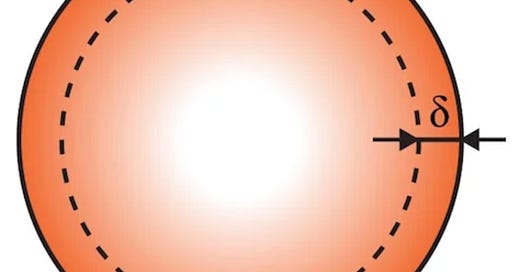
The skin effect is the first effect that I’m going to describe. When an alternative current (AC) flows through a conductor. The skin effect is responsible for affecting the current density distribution on a conductor, having a larger current density at the “skin” of the conductor.
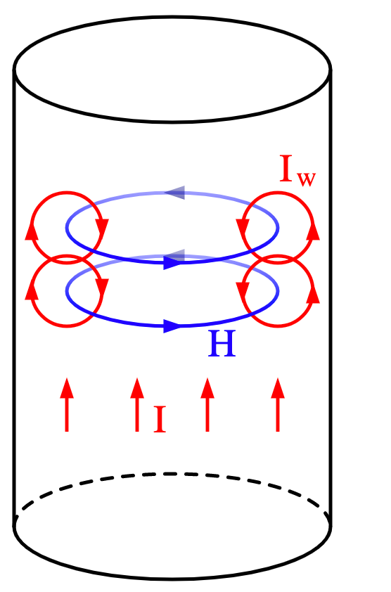
This current produces a magnetic field around the conductor. This magnetic field is also variable, therefore, it produces an electric field in an opposing direction to the main current.
Picture 1. Electric current producing the magnetic field
This electric field (called EMF) is strongest at the center of the conductor and force the main current to conduct through the surface.
Yes…electric current creates an electric field again himself. That remembers me when someone drinks alcohol for dancing better, but a lot of drinks finally are becoming your enemy.
Without entering more physical details, the current density of the main current, distributed in the surface creates the H field created observed in Picture 2 and therefore, the resultant Inductance on the section is higher in the center.
Picture 2. Current, H field and L distribution on a wire section due to High- Frequency current
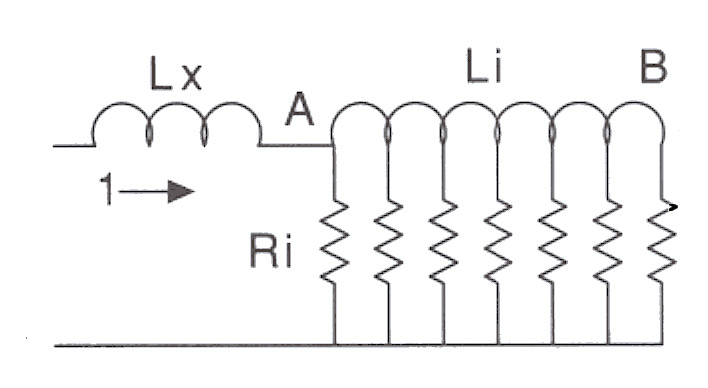
If we try to create the electrical model of the wire section it will look like this.
Picture 3. Wire section electrical model
Point A is the surface and B is the center. Therefore, the path with lower inductance is close to the surface. If we think of the DC resistance case, the distribution is equal for the whole wire.
This effect depends on the frequency. For higher frequencies, the current density on the skin increases dramatically. Here is the equation for calculating the penetration deep, where p is the resistivity of the material, w is the frequency and u is the permeability of the conductor.
Example:
At 1 kHz, the skin deep, where the current will circulate is 2 mm.
At 1 MHz is 65 um.
For the same wire diameter, the current has a much lower area to circulate.
That means the current density on a wire with the same area will be much higher, increasing the losses proportionally.
What can we do to reduce the impact?
We can calculate the skin deep according to the frequency and select a wire diameter similar to the skin deep.
Here, you can find a calculator for any case.
Proximity Effect
The proximity effect appears between conductors of different layers. The Magnetic and the Electric fields are feeding each other in a very romantic way and they deserve a new edition of this Newsletter.
To be continued…
If you liked it and want to receive the next edition in your inbox, just subscribe!
I will do my best to send you a fun newsletter, you can help me if you share this newsletter with your friends. Thank you 😍.


Best wishes on your journey (real and meta).
Always nice to learn new things and refresh topics learned in my electronics engineering career….Electromagnetism is an exciting world !!